Specify Custom Requirements in the App
This topic shows how to specify custom requirements in the Response Optimizer.
You can specify custom requirements, such as minimizing system energy. To specify custom requirements:
In the Response Optimizer, in New drop-down menu, select Custom Requirement. The Create Requirement dialog box opens where you specify the custom requirement.
Specify a requirement name in Name.
Specify the requirement type in the Type drop-down menu.
Specify the name of the function that contains the custom requirement in Function. The field must be specified as a function handle using
@. The function must be on the MATLAB® path. Click to review or edit the
function.
to review or edit the
function.If the function does not exist, clicking
opens a template MATLAB file.
Use this file to implement the custom requirement. The default function
name is myCustomRequirement.(Optional) To prevent the solver from considering specific parameter combinations, select Error if constraint is violated. Use this option for parameter-only constraints.
During an optimization iteration, the solver first evaluates requirements with this option selected.
If the constraint is violated, the solver skips evaluating any remaining requirements and proceeds to the next iteration.
If the constraint is not violated, the solver evaluates the remaining requirements for the current iteration. If any of the remaining requirements bound signals or systems, then the solver simulates the model.
For more information, see Skip Model Simulation Based on Parameter Constraint Violation (GUI).
Note
If you select this check box, then do not specify signals or systems to bound. If you do specify signals or systems, then this check box is ignored.
(Optional) Specify the signal or system, or both, to be bound.
You can apply this requirement to model signals, or a linearization of your Simulink® model (requires Simulink Control Design™ ), or both.
Click Select Signals and Systems to Bound (Optional) to view the signal and linearization I/O selection area.
To apply this requirement to a model signal:
In the Signal area, select a logged signal to which you will apply the requirement.
If you have already selected a signal to log, as described in Specify Signals to Log, it appears in the list. Select the corresponding check box.
If you have not selected a signal to log:
Click
 . A Create Signal Set
dialog box opens where you specify the logged signal.
. A Create Signal Set
dialog box opens where you specify the logged signal.In the Simulink model window, click the signal to which you want to add a requirement.
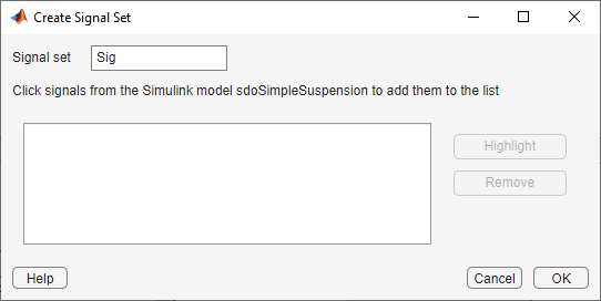
The Create Signal Set dialog box updates and displays the name of the block and the port number where the selected signal is located.
In Signal set field, enter a name for the selected signal set.
Click OK. A new variable, with the specified name, appears in the Data area of the Response Optimizer.
To apply this requirement to a linear system:
Specify the simulation time at which the model is linearized in Snapshot Times. For multiple simulation snapshot times, specify a vector.
Select the linearization input/output set from the Linearization I/O area.
If you have already created a linearization input/output set, it appears in the list. Select the corresponding check box.
If you have not created a linearization input/output set, click
to open the Create linearization I/O
set dialog box. For more information on using this dialog box, see Create Linearization I/O Sets.
For more information on linearization, see What Is Linearization? (Simulink Control Design).
Click OK.
A new variable, with the specified name, appears in the Data area of the Response Optimizer. A graphical display of the requirement also appears in the Response Optimizer app window.
Related Topics
You can also select a web site from the following list:
Americas
- América Latina (Español)
- Canada (English)
- United States (English)
Europe
- Belgium (English)
- Denmark (English)
- Deutschland (Deutsch)
- España (Español)
- Finland (English)
- France (Français)
- Ireland (English)
- Italia (Italiano)
- Luxembourg (English)
- Netherlands (English)
- Norway (English)
- Österreich (Deutsch)
- Portugal (English)
- Sweden (English)
- Switzerland
- United Kingdom (English)